Height adjustment router table
Installing electrical height adjustment on a router table (--> German)
Router: Casals (Freud) CT3000 VCE
alternatively (Casals not available any more): Trend T11
Table: who cares, I use an Incra table
Intro
The router Casals CT3000 allows height adjustment through the table. Due to the fine screw thread the adjustment with the hexagon socket is annoying nevertheless. Furthermore, if you want to avoid calculations and counting the turns, frequently measurement of actual height is necessary to get what you want.That's fact also for other woodworkers, there are many modifications of the height calibration using cordless screwdrivers (but also bowden cable and car jacks). However, frequent measurement of final height remains an issue. Furthermore, fast rotation of the spindle may result in additional problems (Reconstruction against heat-sealing).
The solution described here should not be considered as instructions to follow, it is just the way I did it. There is no guarantee for completeness or even correctness. I don't take over responsibility for damage to property or persons!
Overview
I have connected the spindle of my router to a stepper-motor. The Motor spins the spindle by 1.8° per step, a complete turn is reached after 200 steps. Based on a spindle pitch of 1.5 mm the router bit moves exactly by 1.5/200 = 0.0075 mm per step (disregarding the tolerance of the whole system, especially of the spindle nut). That precision is more than enough for woodworking, and it is reproducible. I drive the motor with 400 Steps/s, that's a speed of 3 mm/s. | ||
| Modified router, the stepper is fixed on the aluminum plate at the top of the picture |
 |
| The stepper in more detail |
Once calibrated with the correct height, the router bit can be driven to any other height precisely and reproducible. The target value can be selected using the control knob. The system is extremely compact, the modification does use small additional space, only. After detaching the stepper power (4-pin molex), the router can still be removed from the table like before the mod.
The usual procedure with my installation is the following:
1. Mount the router bit and measure the actual height

2. Press the Set-knob for 2 seconds activates the SET mode. Use the control dial to enter the measured height, the router bit does not move. Finish SET-mode by pressing the Set-knob again. The system is calibrated.

3. Use the control dial to enter any target values, the bit will immediately follow the target height. Pressing the control dial toggles the increment between 0.1 mm and 0.5 mm..

Pressing the control dial for 2 seconds enters LOCK-mode - avoiding unintentional inputs. The only possible input is pressing the control dial another 2 seconds to unlock the inputs.
Material
Since the original setup was rough-running, I did two modifications on the hardware of the router:- I removed the springs from the router, that hold it away from the work piece. Upside-down, gravity takes care of that.
Since the height adjustment limits only the maximum deflection, the router stands must always be locked before usage!
- I changed the original spindle into a trapezoid spindle:
- Trapezoid spindle TR8x1,5 right DIN103 1 mtr. (~10€)
- Trapezoid spindle nut TR8x1,5 re RG7 rund 22x20 (~15€)
- Shaft coupling D18L25 6,35/6,35 mm (~6€) to mount the stepper with the spindle.
- an Arduino Mega2560 as a small computer (~12€),
- a Prototype Shield ProtoShield V3 to solder the wires (~5€),
- a Dual VNH2SP30 Stepper Motor Driver Module 30A Monster Moto Shield (~18€),
- a SainSmart IIC/I2C/TWI Serial 20x4 LCD 2004 Module as display (~10€),
- a KY-040 Rotary Encoder Module Brick Sensor for height input (~2€),
- a vandalism-knob for mode selection (~10€),
- a Stepper Motor (~20€),
- two end-switches ME8108 to limit movement in both directions (~15€),
- a USB-power supply for the Arduino (~5€) and
- a power supply MEAN WELL HLG-60H-15B for the stepper (~35€)
- NO resistors, capacitors, inductors, diodes, ...
 |
| The position for the router (router not build in): the end switches are triggered by the aluminum plate. They can be moved using the T-slot of the table. Behind the switches, you can see the power supply for the router and USB. |
How does it work?
The Arduino, the Prototype Shield and the Stepper Shield can be placed on each other. No soldering, no screws. The Arduino stays completely unchanged
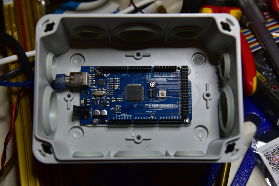 | ||
| The Arduino is placed on the bottom of the box, connected only via USB |
The Stepper Shield gets power from the MEAN WELL power supply. The four outputs of the Stepper-Shield are connected to the stepper, pairwise to both inductors. The Stepper is operated at 15V and 1.8A. The power supply delivers up to 4A, but it is adaptable by a PWM-input. 4A are delivered at 10V at the PWM-input. The Arduino delivers a PWM signal with 4.5V (5V-Signal with 90% pulse duty factor) limiting the power supply to the desired 1.8A. That way, I can adjust the power current in the range of 0-2A.
 | |
| The Stepper-Shield in red. On the left (black/red) the connections to the power supply, both brown connectors on the right are connected to the stepper |
Since the Arduino has only 5V, the range between 2-4A cannot be used without further Work, but it's also not necessary.
All other connections are done using the Prototype Shield.
- The Vandalism knob and both end switches put a pin to GND (see source code). These pins are pulled-up internally to 5V by the Arduino ("Low-active").
The end switches have a big hysteresis. That means, once a switch is closed it must be driven back by several millimeters to open the switch again. Thus, if a switch is closed, that does not necessarily mean the current position is above the limit, but may be caused by the hysteresis. Therefore, the program starts in INIT-mode and drives the router to a center position where both end switches are open. - The control knob is connected in a similar way, a Pull-Up is integrated in the module. The encoder has 5 connectors: GND, VCC (5V from the Arduino as Pull-Up, always connect it, or remove the Pull-Ups!), two pins coding the direction, and a press signal. Decoding is performed using the Arduino-Library "Encoder".
- The LCD-module has 4 connections: GND, VCC, and 2 pins for the I2C-bus. The display is controlled by the "LiquidCrystal_I2C"-library. Do not write too much or too often to the display! First, "setCursor" and "print" are really slow and disturb the smooth positioning of the stepper. Furthermore, fast changes on the display don't look nice. More than 2-3 Hz should not be used.
 |
| On the right side, the Proto-Shield on the Arduino-Board with the wiring, on the left the display, below press button and control knob |
Another useful Library for the project is called "AccelStepper". That simplifies the control of the stepper drastically. After defining maximum speed and acceleration, the library allows smooth transitions to target values.
For programming, I used the Arduino-IDE Software. Simply
- connect the Arduino-Board via USB with your PC,
- install necessary drivers automatically,
- open the source code and
- first compile and
- then transfer the code to the Board.
- Missing Libraries can be searched and installed using "Sketch/Bibliothek einbinden/Bibliothek verwalten".
#include <Wire.h>
#include <LiquidCrystal_I2C.h>
#include <AccelStepper.h>
#include <Encoder.h>
#define DEFAULT_ALLOW 20000
AccelStepper stepper(AccelStepper::FULL4WIRE,7,8,4,9); // INA1, INB1, INA2, INB2
bool initialized=false;
int lastInc=-1;
int lastSwitch = 0;
int height=0;
int factor=5;
int factorPrint=0;
bool stepperDisabled=false;
bool lowerReached=false;
bool upperReached=false;
const int pwmA = 5;
const int pwmB = 6;
const int inc1 = 18;
const int inc2 = 19;
Encoder enc(inc2,inc1);
const int incSwitch = 37;
const int lowerBound=38;
const int upperBound=39;
const int setSwitch=47;
const int currentSet=44;
const int currentSwitch[2]={A2,A3}; // A2 and A3 to get current from motor shield
int lastHeight=-1;
int posOffset=0;
int minAllowed=-DEFAULT_ALLOW;
int maxAllowed=+DEFAULT_ALLOW;
int current=0;
int currentPrint=-1;
bool locked = false;
bool setValueMode=false;
bool setSwitchMode = false;
long lastEncoder=0;
long setSwitchStartTime = 0;
long lastPrint = 0;
long lastCurrentPrint = 0;
int lastPowerCurrent=9999; // Force print
long lastIncTime = 0;
const float conversion=20/1.5;
LiquidCrystal_I2C lcd(0x3f,20,4); // set the LCD address to 0x3f for a 20 chars and 4 line display
void setup()
{
pinMode(incSwitch, INPUT);
digitalWrite(incSwitch, HIGH);
pinMode(lowerBound, INPUT);
digitalWrite(lowerBound, HIGH);
pinMode(upperBound, INPUT);
digitalWrite(upperBound, HIGH);
pinMode(setSwitch, INPUT);
digitalWrite(setSwitch, HIGH);
pinMode(currentSwitch[0], INPUT);
pinMode(currentSwitch[1], INPUT);
pinMode(pwmA, OUTPUT);
pinMode(pwmB, OUTPUT);
pinMode(currentSet, OUTPUT);
setPowerSupply(1.8);
digitalWrite(pwmA, HIGH);
digitalWrite(pwmB, HIGH);
stepper.setMaxSpeed(400);
stepper.setAcceleration(600);
lcd.init(); // initialize the lcd
lcd.init();
// Print a message to the LCD.
lcd.backlight();
lcd.setCursor(0,0);
lcd.print("Router Control:");
setMode("INIT");
Serial.begin(115200); // open the serial port at 115200 bps:
}
void setPowerSupply(float amps)
{
analogWrite(currentSet, amps*255/2.); // power supply delivers 4A@10V, 2A@5V
}
void setMode(const char *a)
{
lcd.setCursor(16,0);
lcd.print(a);
}
void printLCD(int value, bool small=false)
{
char buffer[16];
value+=posOffset;
if (value>=0) buffer[0]='+';
else buffer[0]='-';
if (small)
sprintf(&buffer[1],"%4i.%1i",abs(value)/10,abs(value)%10);
else
sprintf(&buffer[1],"%4i.%1imm",abs(value)/10,abs(value)%10);
lcd.print(buffer);
}
void loop(){
unsigned c[2];
c[0]=analogRead(currentSwitch[0]);
c[1]=analogRead(currentSwitch[1]);
int powerCurrent = 300.*((c[0]>c[1])? c[0]:c[1])/811.;
long newPosition=lastEncoder;
long currentTime=millis();
if (initialized)
newPosition = enc.read();
if (newPosition!=lastEncoder && (abs(newPosition))%4==0)
{
long diff=(newPosition-lastEncoder);
lastEncoder = newPosition;
if (locked)
{
;
}
else if (setValueMode)
{
posOffset+=diff*factor/5;
lcd.setCursor(0,2);
printLCD(current);
lcd.setCursor(0,3);
printLCD(height);
if (minAllowed!=-DEFAULT_ALLOW)
{
lcd.setCursor(0,1);
printLCD(minAllowed, true);
}
if (maxAllowed!=DEFAULT_ALLOW)
{
lcd.setCursor(8,1);
printLCD(maxAllowed, true);
}
}
else
height+=diff*factor;
}
lastEncoder=newPosition;
int val1,val2;
if (stepper.distanceToGo() == 0) {
stepper.disableOutputs();
stepperDisabled=true;
// setPowerSupply(0.2);
stepper.run(); // let the AccelStepper disable motor current after stop
}
stepper.run();
val1 = !digitalRead(incSwitch);
if (val1 || val1!=lastSwitch) // inc button pressed!
{
if (!lastSwitch && val1) // just pressed, store time
lastIncTime = currentTime;
if ((currentTime-lastIncTime>2000) && val1)
{
locked = !locked;
if (locked) setMode("LOCK");
else setMode("WORK");
lastIncTime=currentTime+50000; // avoid toggeling
}
else if (!locked && lastSwitch && !val1) // just released
{
factor = (factor==5)? 50:5;
}
lastSwitch=val1;
}
if ((currentTime-lastCurrentPrint)>500 && lastPowerCurrent != powerCurrent)
{
Serial.println(powerCurrent);
char buffer[8];
lcd.setCursor(14,2);
sprintf(buffer,"%2i.%1iA",powerCurrent/10,abs(powerCurrent)%10);
lcd.print(buffer);
lastPowerCurrent=powerCurrent;
lastCurrentPrint = currentTime;
}
if (factorPrint!=factor)
{
lcd.setCursor(15,3);
if (factor==5) lcd.print("0.5");
else lcd.print("5.0");
factorPrint=factor;
}
bool old=lowerReached;
lowerReached=!digitalRead(lowerBound);
if (old!=lowerReached || lowerReached)
{
if (lowerReached && stepper.distanceToGo()<0 && minAllowed==-DEFAULT_ALLOW)
{
minAllowed=current;
lcd.setCursor(0,1);
printLCD(minAllowed,true);
}
}
old = upperReached;
upperReached=!digitalRead(upperBound);
if (old!=upperReached || upperReached)
{
if (upperReached && stepper.distanceToGo()>0 && maxAllowed==DEFAULT_ALLOW)
{
maxAllowed=current;
lcd.setCursor(8,1);
printLCD(maxAllowed, true);
}
}
old = setSwitchMode;
setSwitchMode=!digitalRead(setSwitch);
if (!locked && setSwitchMode) // pressed
{
if (old!=setSwitchMode) // just pressed
{
setSwitchStartTime = currentTime;
if (setValueMode)
{
setValueMode=false;setMode("WORK");
}
}
else if (currentTime-setSwitchStartTime>2000 && !setValueMode) // pressed for 2 seconds
{
setValueMode=true;setMode("SET!");
}
}
if (height>maxAllowed) height=maxAllowed;
if (height<minAllowed) height=minAllowed;
if (lastHeight!=height)
{
if (stepper.targetPosition()!=height*conversion)
{
if (stepperDisabled)
{
stepper.enableOutputs();
//setPowerSupply(1.8);
stepper.run();
stepperDisabled=false;
delay(50);
}
stepper.moveTo(height*conversion);
stepper.run();
}
// Serial.print("----------------");
// Serial.println(height);
lcd.setCursor(0,3);
printLCD(height);
lastHeight=height;
}
if (stepper.distanceToGo() != 0)
{
current=round(stepper.currentPosition()/conversion);
}
if (currentPrint!=current && abs(currentTime-lastPrint)>300) // print current pos with no more than 3 Hz
{
lcd.setCursor(0,2);
printLCD(current);
currentPrint = current;
lastPrint = currentTime;
}
if (!initialized)
{
if (lowerReached == upperReached)
{
setMode("WORK");
minAllowed= -DEFAULT_ALLOW;
maxAllowed= +DEFAULT_ALLOW;
initialized=true;
}
else if (fabs(stepper.distanceToGo())<25*conversion)
{
if (lowerReached)
height+=50;
else
height-=50;
}
}
}
That's all. Some issues on my ToDo list:
- Currently, heights are always reached the direct way. Since the system has some built-in tolerance it is a difference if the target height is reached from below or from above, of approx. 0.2 mm. That's no Show-Stopper, but could be avoided when always reaching the target value from below. Thus, if the router bits shell be lowered, lower it by 0.5 mm more than necessary, and then drive back to the target height. This change should be software only, but is not implemented yet. Especially with fine adjustments, it might be annoying. Another option: once the target position is reached for 1 or 2 seconds, lower the bit by 0.5 mm and drive it up again.
- Honestly, the display (LCD 2004) is crap. It's inefficiently controlled, slow, badly readable - and should be exchanged by something more sophisticated.
- Since I work frequently with flush trim router bits, and I already had some issues with chipping (depending on the direction of grain), I now often toggle my work piece upside-down. Thus, my template is sometimes above and sometimes below my work piece. I use a flush trim router bit with an upper and lower bearing, and change position often between both. Thus, the thing missing in my installation is some memory keys where I can store positions to easily toggle height, like the memory stations of a radio.
- Instead of manual calibration, this could be performed automatically (an INIT-mode releasing the end switches is already available...)
- One opportunity would be a photo sensor below the table. Problems: dust, need space for vacuum device
- A metal plate that can be located above the router bit could we put to GND by the router bit
- That does not make sense for some router bits (e.g., those with bearings). Also, calibrating the bit wherever you like is more convenient than adjusting to zero.
- Locking the stands is also a big issue.
- In best case, the Arduino would take care of the locking, controlling some kind of motorized/magnetic/hydraulic/whatever locking. I do not want to modify the router itself too much, I do not know how to integrate something like that. Instead of using the original locking mechanism, I would prefer attaching a bar and lock it via some kind of spring-operated locking unit, however this looks really expensive.
- It would be easier to integrate a sensor to detect if the stand is locked. That would allow to avoid moving the router if the stand is locked. You could also disable the router power, if the stand is not locked.
- Re-installing the springs might reduce the problem. I did not try yet if the stepper is capable to fight against the springs.


Kommentare
Kommentar veröffentlichen